


News Center
News Center
Applications of RTCP Ballbar/Probe for Five-Axis Machine Tools
RTCP, in high-end five-axis CNC systems, is understood as Rotated Tool Center Point—commonly referred to as the tool-tip-following function. In five-axis machining, when aiming to precisely control the tool-tip trajectory and the relative orientation between the tool and the workpiece, rotary motions introduce additional motion at the tool tip. Because the CNC system’s commanded tool-center point often does not coincide with the actual tool tip, the system must automatically compensate for this offset to ensure that the tool tip follows the prescribed trajectory as instructed. Within the industry, this technology is also known by other names such as TCPM, TCPC, or RPCP. In essence, all these terms refer to functions with similar capabilities to RTCP; strictly speaking, RTCP is specifically designed for dual-tilt-head configurations, where compensation is performed using the rotation center of the tilting head. By contrast, functions like RPCP are primarily used on machines with dual-rotary-table setups, compensating for changes in the linear-axis coordinates caused by workpiece rotation. Ultimately, however, these functions serve the same fundamental purpose: to maintain a constant relationship between the tool center and the actual contact point between the tool and the workpiece surface.
Release time:
2023-06-27
RTCP, in high-end five-axis CNC systems, is understood to mean Rotated Tool Center Point, which is what we commonly refer to as the tool-tip following function.


Renishaw Ballbar Diebold Probe Rod
Fundamentally, the RTCP function primarily involves modifying the interpolation computation process.

In five-axis machining, when aiming to control the tool-tip trajectory and the orientation of the tool relative to the workpiece, rotary motions introduce additional motion at the tool tip. Because the CNC system’s commanded tool-position points often do not coincide with the actual tool tip, the system must automatically compensate for this offset to ensure that the tool tip follows the prescribed trajectory as instructed. In the industry, this capability is also referred to by terms such as TCPM, TCPC, or RPCP. In essence, the functional definitions of these terms are all similar to RTCP; strictly speaking, RTCP is implemented on machines with dual-tilt-head configurations, where compensation is performed using the rotation center of the tilt head. By contrast, functions akin to RPCP are primarily used on machines with dual-rotary-table setups, compensating for changes in the linear-axis coordinates caused by workpiece rotation. Ultimately, all these functions serve the same purpose: to maintain a constant relationship between the tool center point and the actual contact point between the tool and the workpiece surface.
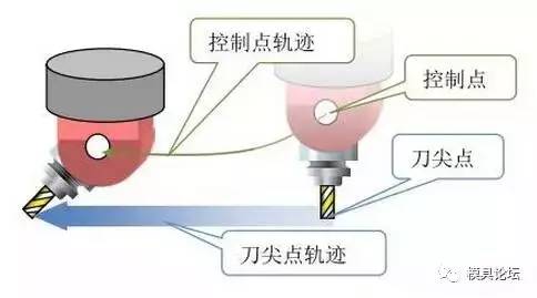
Machine tools equipped with RTCP technology—commonly referred to in the industry as true five-axis machines—eliminate the need for operators to precisely align workpieces with the rotary table’s axis of rotation. Workpieces can be clamped arbitrarily, as the machine automatically compensates for any misalignment, significantly reducing setup time while enhancing machining accuracy. Moreover, post-processing is straightforward: it suffices to output the tool-tip coordinates and tool vectors. From a mechanical standpoint, five-axis CNC machines typically feature configurations such as dual swivel heads, dual rotary tables, or a combination of one swivel head and one rotary table.
Let us take the high-end five-axis CNC system with dual rotary tables as an example to provide a detailed introduction to the RTCP function.
In a five-axis machine tool, the concepts of the fourth and fifth axes are defined as follows: in a dual-rotary table configuration, rotation about the fourth axis affects the orientation of the fifth axis, whereas rotation about the fifth axis does not affect the orientation of the fourth axis. The fifth axis is a rotary coordinate about the fourth axis.
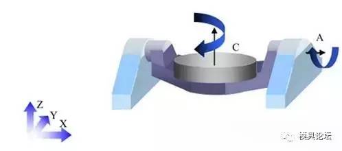
As shown in the figure above, the machine tool’s fourth axis is the A axis, and the fifth axis is the C axis. The workpiece is mounted on the C-axis rotary table. When the A axis rotates, since the C axis is mounted on the A axis, the orientation of the C axis is also affected. Similarly, for the workpiece mounted on the rotary table, if we program the tool center point for cutting, any change in the rotational coordinates will inevitably lead to changes in the linear X, Y, and Z coordinates, resulting in a relative displacement. To eliminate this displacement, the machine tool must apply compensation; RTCP is the function specifically designed to eliminate this compensation.
So how does the machine tool compensate for this offset? Next, we will analyze how this offset arises.
As discussed earlier, we know that the offset in the linear axis coordinates is caused by changes in the rotating coordinate system. Therefore, it is particularly important to analyze the rotation center of the rotary axis. For machine tools with a dual-turntable configuration, the control point for the C-axis—also known as the fifth axis—is typically located at the rotational center of the machine table. As for the fourth axis, the control point is usually set at the midpoint of the fourth-axis spindle line.
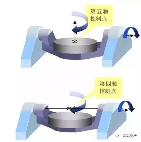
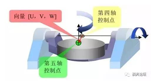
To implement five-axis control, the CNC system must determine the relationship between the fifth-axis control point and the fourth-axis control point. Specifically, under the fourth-axis rotary coordinate system whose origin is the fourth-axis control point in the initial state (with the machine tool’s A and C axes at their zero positions), the position vector of the fifth-axis control point is [U, V, W]. In addition, the distance between the A and C axis centers must be known. For a dual-rotary-table machine tool, an example is shown in the figure below.
As you can see, for machine tools equipped with RTCP functionality, the control system ensures that the tool center remains precisely at the programmed position at all times. In this scenario, programming is independent and decoupled from the machine tool’s motion. When you program on the machine tool, you need not worry about the machine’s movement or tool length; your sole concern is the relative motion between the tool and the workpiece. The control system takes care of everything else. For example:
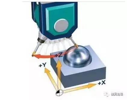
As shown in the figure above, when RTCP is disabled, the control system does not account for tool length. The tool rotates about the spindle center, causing the tool tip to move away from its original position and no longer remain fixed.
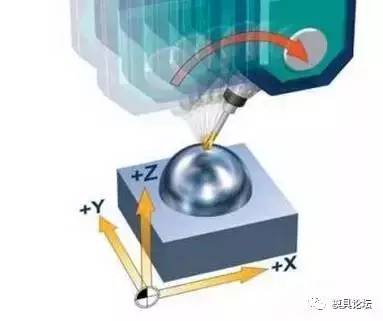
As shown in the figure above, with RTCP enabled, the control system only adjusts the tool orientation while keeping the tool tip position unchanged. The necessary compensation movements along the X, Y, and Z axes are automatically calculated and applied.
So how do five-axis machine tools and CNC systems that lack RTCP address the issue of linear-axis coordinate offsets? As we know, many domestically produced five-axis CNC machines and systems today are what are referred to as “pseudo-five-axis” machines—meaning they do not incorporate RTCP functionality. Whether a machine is “true” or “pseudo” five-axis has nothing to do with its physical appearance or whether all five axes can simultaneously interpolate; in fact, even pseudo-five-axis machines can perform five-axis simultaneous machining. The key distinction lies in the absence of a true five-axis RTCP algorithm, which means that programming for such machines requires accounting for the spindle swing radius and the position of the rotary table. Consequently, when using pseudo-five-axis CNC systems and machines, programmers must rely on CAM software and post-processing to pre-plan toolpaths in advance.
For the same part, whenever the machine tool or cutting tool is changed, CAM programming and post-processing must be redone from scratch. Moreover, with a pseudo-five-axis machine, workpiece clamping requires that the workpiece be positioned precisely at the rotary center of the machine table; for the operator, this means substantial setup and alignment time, with no guarantee of accuracy. Even when performing indexed machining, pseudo-five-axis systems are far more cumbersome. In contrast, a true five-axis system only requires setting up a single coordinate system and performing a single tool-setting operation to complete the entire machining process.
Pseudo-five-axis machining relies on post-processing to define the spatial relationship between the machine tool’s fourth and fifth axes, thereby compensating for the displacement of linear-axis coordinates caused by rotary-axis motion. The resulting CNC program not only specifies the X, Y, and Z approach points but also incorporates the necessary compensation for the X, Y, and Z axes. However, this approach leads to insufficient machining accuracy, low efficiency, non-universal programs, and high labor costs. Moreover, since each machine tool has different rotary-axis parameters, a dedicated post-processor file is required for every machine, which creates significant operational inconvenience. Furthermore, pseudo-five-axis programs cannot be modified, making manual five-axis programming virtually impossible.
At the same time, due to the lack of RTCP functionality, many advanced five-axis features that depend on it—such as five-axis tool compensation—cannot be utilized. In fact, for a five-axis machine tool, it is merely a tool we use to achieve the desired machining results; there is no inherent distinction between “true” and “false” five-axis machines. What matters most is that our machining process dictates which approach to adopt; comparatively speaking, true five-axis machines offer better value for money.
RTCP, tool-tip following function, ballbar,,ball-end probe, five-axis RTCP
Recent Updates


2026-03-30

2026-02-13

2026-01-31
Contact Us


Room 105, Building 8, Zone 8, Lingxin Market, Jiangning District, Nanjing City